ARKit Theory: Vertices, Metal Shaders, UV Mapping and SCNProgram’s.
Across my journey into Augmented Reality, there was nothing more than I feared than Shaders. Preached as the highest difficulty in the entire programming universe; OpenGL, GLSL or Metal Shaders are a type of computer program which performs a custom rendering.

A render of a 3d mesh.
Across my journey into Augmented Reality, there was nothing more than I feared than Shaders. Preached as the highest difficulty in the entire programming universe; OpenGL, GLSL or Metal Shaders are a type of computer program which performs a custom rendering.
In other words: A shader acts as an objects ‘material’, making an object look the way it does, through code.
Cool, but how exactly does it do this ? What are the factors ? And how does one exactly connect a shader to a geometry ? I’m already confused, can we start again.
Fear not, let’s start with Vertices.
Download an AR camera starter project
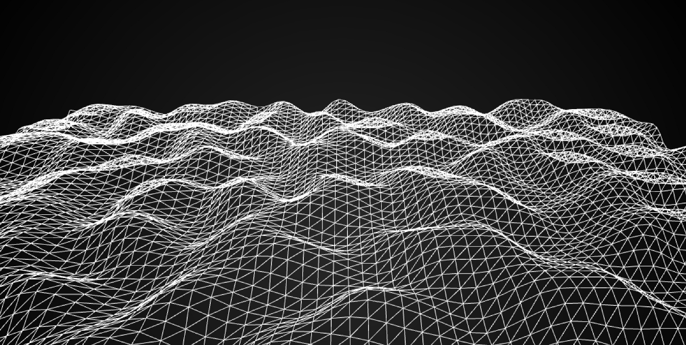
A representation of a sea of vertices, shaded in a wireframe material.
Vertices
Vertices, which is the plural of Vertex, are points at which two polygon edges of a polygon meet. Below are examples of vertices that form a shape, each represented by a letter.
A series of shapes, whose vertices are labeled by letters.
Now here’s the twist: Vertices define how a computer renders an object.
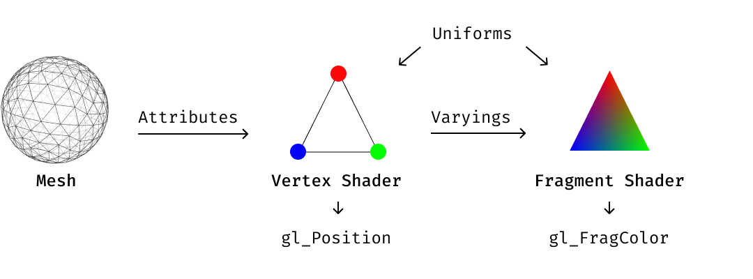
To walk you through how a computer does this, let’s consider a basic triangle, with a shader that attaches a different primary color to each of its three vertices.
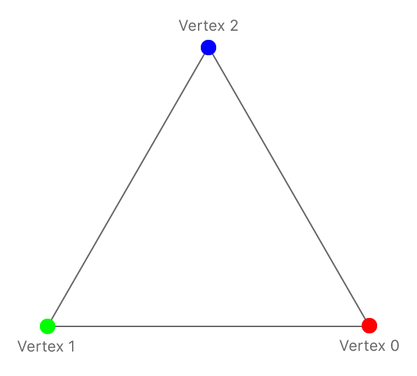
A triangle with vertices given different primary colors.
A triangle with vertices given different primary colors.
Through the shaders ‘Fragment shader’ (explained later), the computer renders the triangle to look like this (apologies for the rotation of vertices):
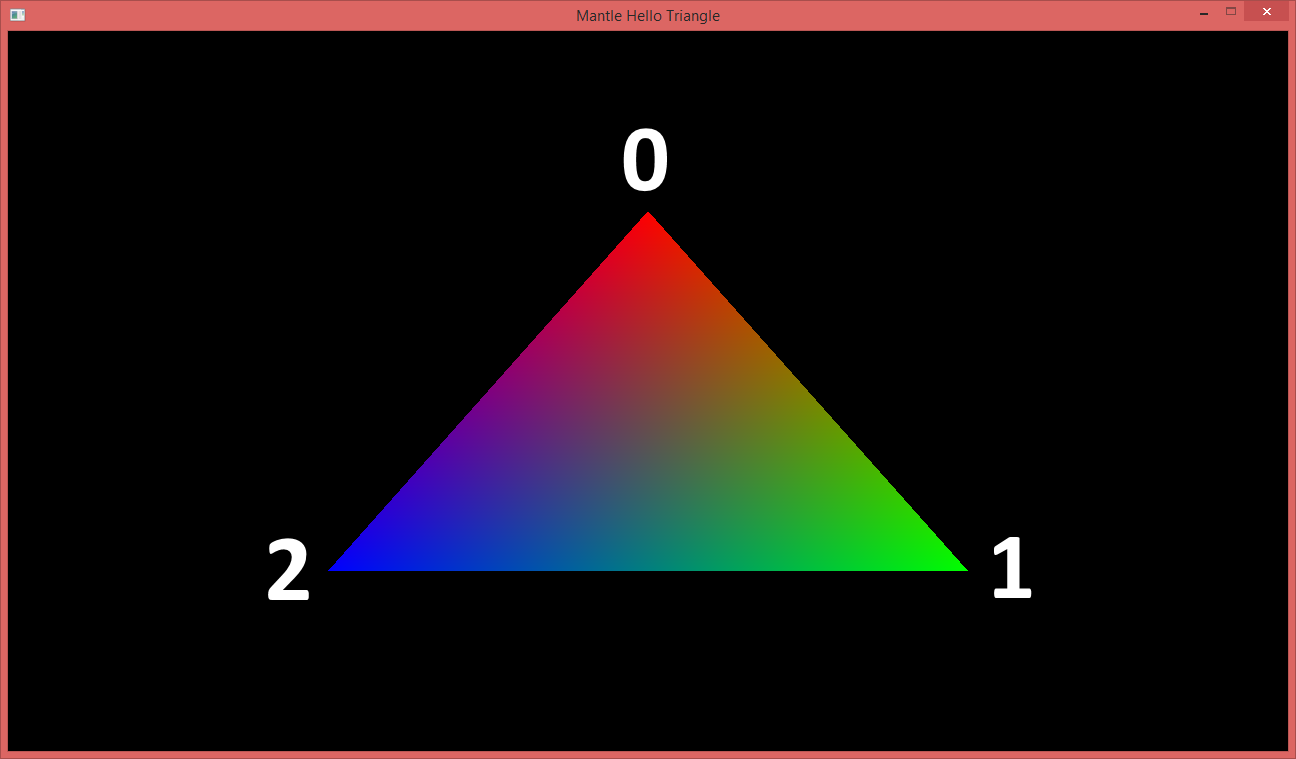
A triangle with vertices given different primary colors.
As you can see from the two images, each vertex holds a color which is then interpolated (as a gradient) between vertices of each triangle to create the right aesthetic. i.e. green must turn to red, between 1 and 0, for it to be correct.
Shaders
Now that you understand Vertices, let’s dive into what shaders do.
As mentioned above, a shader acts as an objects ‘material’, making an object look the way it does, through code.
It achieves this through the following ‘pipeline’:
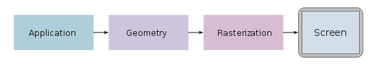
A graphics pipeline structure.
Incase you’re a visual thinker, this is what it looks like:
A graphics pipeline structure.
These diagrams tell us that the way an application uses a shader is it loads up the geometry, and passes the attribute information to the vertex shader — which is responsible for manipulating properties such as position, color and texture coordinates, but cannot create new vertices.
The output of the vertex shader goes to the next stage in the pipeline, which is is the Fragment Shader — which is also known as a Pixel Shader, which computes color and other attributes of each “fragment” — a technical term usually meaning a single pixel. [Source]
Given this analysis, the image below could be a simple 2D plane with hundreds of vertices which are altered within time and space by a vertex shader.
This sea of vertices is a plane whose vertices have been altered by a vertex shader.
Here’s a standard metal shader, that renders the material in white:
This shader takes in an input vertex of type Vertex, defined in line 41, passes it through the Vertex Shader, line 50 to line 59 and then through the Fragment shader, line 63 to 72.
Neat. But how do I attach it to the geometry in ARKit ?
SCNProgram
A SCNProgram is a complete Metal or OpenGL shader program that replaces SceneKit’s rendering of a geometry or material.
It essentially ties a vertex and fragment shader to a geometry through a material. Here’s the code to attach a shader with transparency to a child, please change the shaderName to Standard to make it work with the shader above.
UVMapping
Now that you have that running, you might be wondering how do you manipulate a specific vertex within a model ? Or how do I make sense of a 3D geometry ?
The answer to this is UV Mapping — a diagram which represents the 3D object in 2D and which can be manipulated using tools like Maya.
Here’s a direct output of a cylinder UV map from Maya. Please note that the vertical edge (represented by V) and the horizontal edge (represented by U) ranges from 0 to 1.
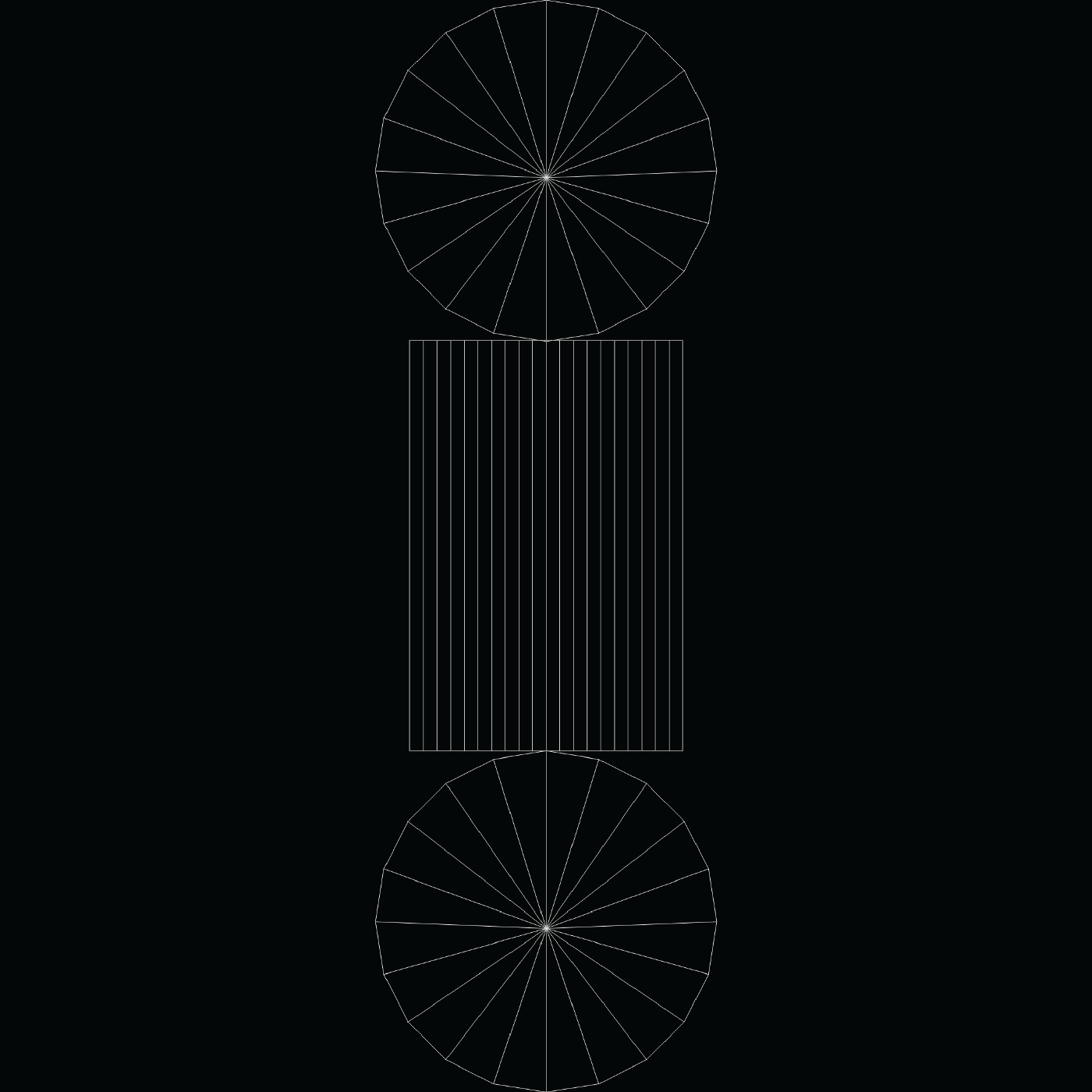
A basic Cylindrical UV Mapping
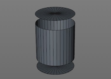
This UV mapping represents a cylinder like the one below:
To modify specific vertices, you must get their UV location and use it to filter what you want to do with the vertex — whether its color, position or other.
Let’s say you want to show the vertices over time, like I have done previously in my stroke shader (below)
As you can see, this takes the input vertex and uses where the vertex finds itself in space to decide whether to show it or not (line 81). If it isn’t in a location that should be shown, it discards it — or does not render it.
That's a wrap
Please email us any questions that you may have using the contact form.